
- Sopto Home
-

- SPT-GCXX1G-80(D) 1.25Gbps GBIC CWDM Optical Transceiver, 80km Reach
- Fiber Optic Transceiver Module
- High Speed Cable
- Fiber Optical Cable
- Fiber Optical Patch Cords
- Splitter CWDM DWDM
- PON Solution
- FTTH Box ODF Closure
- PCI-E Network Card
- Network Cables
- Fiber Optical Adapter
- Fiber Optical Attenuator
- Fiber Media Converter
- PDH Multiplexers
- Protocol Converter
- Digital Video Multiplexer
- Fiber Optical Tools
- Compatible
SPT-GCXX1G-80(D) 1.25Gbps GBIC CWDM Optical Transceiver, 80km Reach

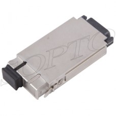
SPT-GCXX1G-80(D)
1.25Gbps GBIC CWDM Optical Transceiver, 80km Reach
Features
Dual data-rate of 1.25Gbps/1.0625Gbps operation
9 CWDM DFB wavelengths laser and PIN photo detector for 80km transmission
Duplex SC optical interface
Standard serial ID information compatible with SFF-8053
+3.3V/5Vsingle power supply
RoHS Compliant
Operating case temperature: 0 to +70℃
Applications
Switch to Switch interface
Switched backplane applications
Router/Server interface
Other optical transmission systems
Description
The GBIC transceiver is high performance, cost effective module supporting dual data-rate of 1.25Gbps/1.0625Gbps and from 80km transmission distance with SMF. The transceiver consists of two sections: The transmitter section incorporates a DFB laser. And the receiver section consists of a PIN photodiode integrated with a trans-impedance preamplifier (TIA). All modules satisfy class I laser safety requirements. The optical output can be disabled by a TTL logic high-level input of Tx Disable. Tx Fault is provided to indicate degradation of the laser. Loss of signal (LOS) output is provided to indicate the loss of an input optical Signal of receiver. The standard serial ID information Compatible with GBIC MSA describes the transceiver’s capabilities, standard interfaces, manufacturer and other information. The host equipment can access this information via the two-wire serial CMOS EEPROM protocol. For further information, please refer to SFF-8053.
Absolute Maximum Rating
Stress in excess of the maximum absolute ratings can cause permanent damage to the module.
|
Parameter |
Symbol |
Min |
Typical |
Max |
Unit |
|
Maximum Supply Voltage |
Vcc |
0.5 |
- |
4.5 |
V |
|
Storage Temperature |
TS |
-40 |
- |
+85 |
℃ |
|
Relative Humidity |
RH |
0 |
- |
+85 |
% |
Recommended Operating environment
|
Parameter |
Symbol |
Min |
Typical |
Max |
Unit |
||
|
Operating Case Temperature |
Standard |
TC |
0 |
- |
+70 |
℃ |
|
|
Power Supply Voltage |
VCC |
3.1 |
|
5.5 |
V |
||
|
Power Supply Current |
Icc |
|
|
300 |
mA |
||
|
Data Rate |
Gigabit Ethernet |
|
|
1.25 |
|
Gbps |
|
|
Fiber Channel |
|
|
1.0625 |
|
|||
SPT-GCXX1G-80(D)
|
λC Wavelength Guide |
|||||
|
Code |
λC |
Unit |
Code |
λC |
Unit |
|
45 |
1450 |
nm |
55 |
1550 |
nm |
|
47 |
1470 |
nm |
57 |
1570 |
nm |
|
49 |
1490 |
nm |
59 |
1590 |
nm |
|
51 |
1510 |
nm |
61 |
1610 |
nm |
|
53 |
1530 |
nm |
|
|
|
Optical and Electrical Characteristics
SPT-GCXX1G-80(D): CWDM DFB and PIN, 80km, (Operating case temperature TC=25℃, VCC=3.3V)
|
Parameter |
Symbol |
Min |
Typical |
Max |
Unit |
Notes |
|
|
Transmitter |
|||||||
|
Spectral Width (-20dB) |
σ |
|
|
1 |
nm |
|
|
|
Side Mode Suppression Ratio |
SMSR |
30 |
|
|
dB |
|
|
|
Average Output Power |
P0ut |
0 |
|
+5 |
dBm |
1 |
|
|
Extinction Ratio |
ER |
9 |
|
|
dB |
|
|
|
Output Optical Eye |
IEEE802.3z and ANSI Fiber Channel Compatible |
2 |
|||||
|
Data Input Swing Differential |
VIN |
200 |
|
2400 |
mV |
3 |
|
|
Input Differential Impedance |
ZIN |
90 |
100 |
110 |
Ω |
|
|
|
TX Disable |
Disable |
|
2.0 |
|
Vcc |
V |
|
|
Enable |
|
0 |
|
0.8 |
V |
|
|
|
TX Fault |
Fault |
|
2.0 |
|
Vcc+0.3 |
V |
|
|
Normal |
|
0 |
|
0.8 |
V |
|
|
|
Receiver |
|||||||
|
Receiver Sensitivity |
|
|
|
-23 |
dBm |
4 |
|
|
Receiver Overload |
|
-3 |
|
|
dBm |
4 |
|
|
Optical Path Penalty |
|
|
|
1 |
dB |
5 |
|
|
LOS De-Assert |
LOSD |
|
|
-24 |
dBm |
|
|
|
LOS Assert |
LOSA |
-30 |
|
|
dBm |
|
|
|
LOS Hysteresis |
|
1 |
|
4 |
dB |
|
|
|
Data Output Swing Differential |
VOUT |
600 |
|
1000 |
mV |
6 |
|
Notes:
1. The optical power is launched into SMF.
2. Measured with a PRBS 27-1 test pattern @1250Mbps.
3. PECL input, internally AC coupled and terminated.
4. Measured with a PRBS 27-1 test pattern @1250Mbps, BER ≤1×10-12.
5.Measured with a PRBS 2 -1 test pattern @1250Mbps, over 20km G.652 SMF, BER ≤1×10
6. Internally AC coupled.
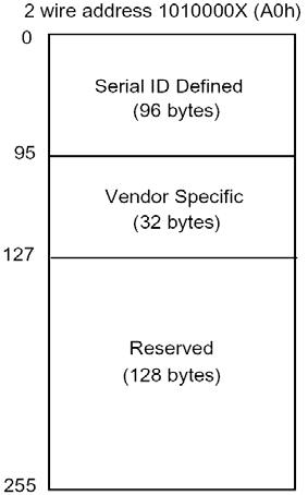
EEPROM Section
The SFF-8053 defines a 256-byte memory map in EEPROM describing the transceiver’s capabilities, standard interfaces, manufacturer, and other information, which is accessible over a 2 wire serial interface at the 8-bit address 1010000X (A0h).
Pin Definitions
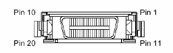
|
Pin Name |
Pin# |
Name/Function |
Signal Specification |
|
|
Receiver Signals |
||||
|
RGND |
2,3, 11,14 |
Receiver Ground (maybe connected with TGND in GBIC) |
Ground, to GBIC |
|
|
VDDR |
15 |
Receiver +3.3/5 volt (maybe connected with VDDT in GBIC) |
Power, to GBIC |
|
|
-RX_DAT |
12 |
Receive Data, Differential PECL |
High speed serial. From GBIC |
|
|
+RX_DAT |
13 |
Receive Data, Differential PECL |
High speed serial. From GBIC |
|
|
RX_LOS |
1 |
Receiver Loss of Signal, logic high, open collector compatible, 4.7k to 10kΩ pullup to VDDT on host |
Low speed, from GBIC |
|
|
Transmitter Signals |
||||
|
TGND |
8,9,17,20 |
Transmitter Ground (maybe connected with RGND internally) |
Ground, to GBIC |
|
|
VDDT |
16 |
Transmitter +3.3/5 volt (maybe connected with VDDR in GBIC) |
Power, to GBIC |
|
|
-TX_DAT |
18 |
Transmit Data, Differential PECL |
High speed serial, to GBIC |
|
|
+TX_DAT |
19 |
Transmit Data, Differential PECL |
High speed serial, to GBIC |
|
|
TX_DISABLE |
7 |
Transmitter Disable, logic high, open collector compatible, 4.7k to 10kΩ pullup to VDDT on GBIC |
Lows peed, to GBIC |
|
|
TX_FAULT |
10 |
Transmitter, Fault, logic high, open collector compatible, 4.7k to 10kΩ pullup to VDDT on host |
Lows peed, from GBIC |
|
|
Controlsignals |
||||
|
MOD_DEF(0) |
4 |
TTL low, output |
Pleasereference SFF-8053, Annex D; Module definition "4" |
|
|
MOD_DEF(1) |
5 |
SCL serial clock signal, input |
||
|
MOD_DEF(2) |
6 |
SDA serial data signal, input/output |
||
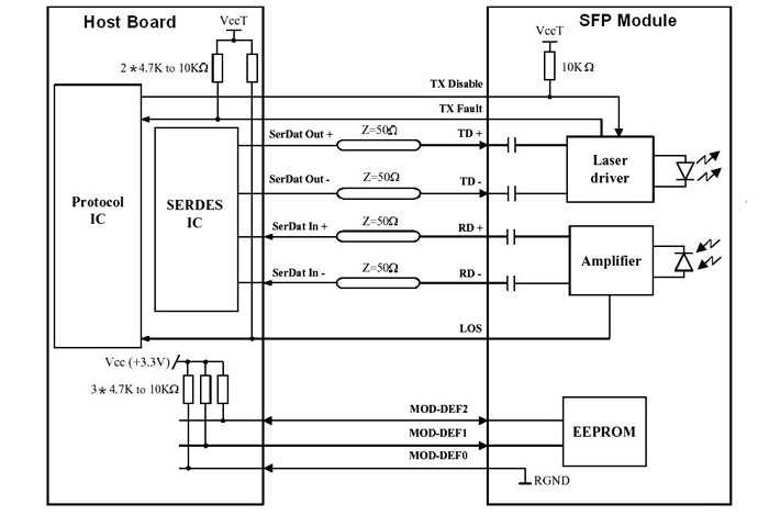
Block Diagram of Transceiver
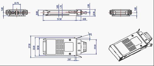
Mechanical Dimensions
Ordering Information
|
Part number |
Product Description |
|
SPT-GC451G-80 |
CWDM 1450nm, 1.25Gbps, 80km, 0ºC~+70ºC |
|
SPT-GC471G-80 |
CWDM 1470nm, 1.25Gbps, 80km, 0ºC~+70ºC |
|
SPT-GC491G-80 |
CWDM 1490nm, 1.25Gbps, 80km, 0ºC~+70ºC |
|
SPT-GC511G-80 |
CWDM 1510nm, 1.25Gbps, 80km, 0ºC~+70ºC |
|
SPT-GC531G-80 |
CWDM 1530nm, 1.25Gbps, 80km, 0ºC~+70ºC |
|
SPT-GC551G-80 |
CWDM 1550nm, 1.25Gbps, 80km, 0ºC~+70ºC |
|
SPT-GC571G-80 |
CWDM 1570nm, 1.25Gbps, 80km, 0ºC~+70ºC |
|
SPT-GC591G-80 |
CWDM 1590nm, 1.25Gbps, 80km, 0ºC~+70ºC |
|
SPT-GC611G-80 |
CWDM 1610nm, 1.25Gbps, 80km, 0ºC~+70ºC |
|
SPT-GC451G-80D |
CWDM 1450nm, 1.25Gbps, 80km, 0ºC~+70ºC, DDM |
|
SPT-GC471G-80D |
CWDM 1470nm, 1.25Gbps, 80km, 0ºC~+70ºC, DDM |
|
SPT-GC491G-80D |
CWDM 1490nm, 1.25Gbps, 80km, 0ºC~+70ºC, DDM |
|
SPT-GC511G-80D |
CWDM 1510nm, 1.25Gbps, 80km, 0ºC~+70ºC, DDM |
|
SPT-GC531G-80 |
CWDM 1530nm, 1.25Gbps, 80km, 0ºC~+70ºC, DDM |
|
SPT-GC551G-80 |
CWDM 1550nm, 1.25Gbps, 80km, 0ºC~+70ºC, DDM |
|
SPT-GC571G-80 |
CWDM 1570nm, 1.25Gbps, 80km, 0ºC~+70ºC, DDM |
|
SPT-GC591G-80 |
CWDM 1590nm, 1.25Gbps, 80km, 0ºC~+70ºC, DDM |
|
SPT-GC611G-80 |
CWDM 1610nm, 1.25Gbps, 80km, 0ºC~+70ºC, DDM |
E-mail:sales@sopto.com